Installation Instructions
Download the Cut Sheet
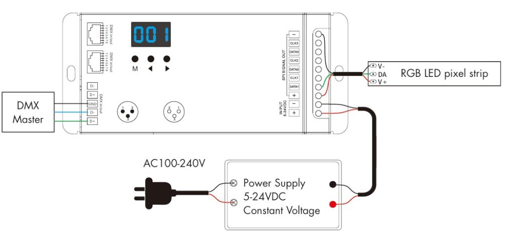
Strip Connection for Less Than 10 Amps
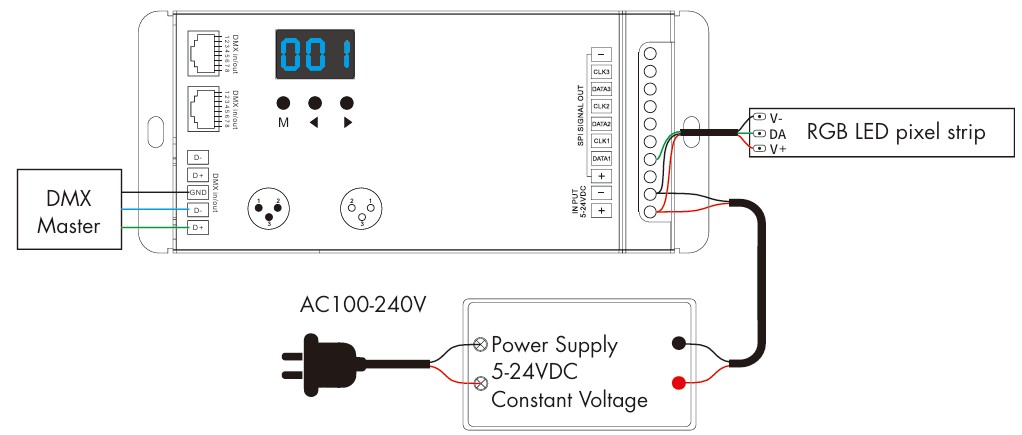
Strip Connection for Over 10 Amps
Operation
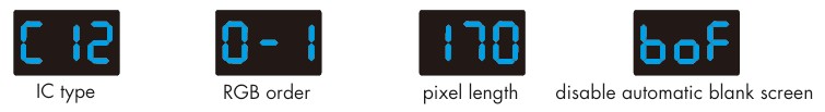
- First verify or change the IC (LED chip) type, RGB order (if different), and pixel length.
- To do this, long press the M and < buttons at the same time. Short press the M key to switch between the settings and use the arrow keys to set the value for each. To exit this menu, you can long press the M key for 2 seconds or wait 10 seconds (if at any point there are 10 seconds between key presses, it will exit the menu).
IC Types Supported
| DMX Decoder Value |
IC Type |
Output Wire Signal |
| C11 |
TM1803 |
DATA |
| C12 |
TM1809, TM1804, TM1812, UCS1903, UCS1909, UCS1912, SK6813, UCS2903, UCS2909, UCS2912, WS2811, WS2812, WS2813, WS2815, SM16703P |
DATA |
| C13 |
TM1829 |
DATA |
| C14 |
TLS3001, TLS3002 |
DATA |
| C15 |
GW6205 |
DATA |
| C16 |
MBI6120 |
DATA |
| C17 |
TM1814B (RGBW) |
DATA |
| C18 |
SK6812 (RGBW), WS2813 (RGBW), WS2814 (RGBW) |
DATA |
| C19 |
UCS8904B (RGBW) |
DATA |
| C21 |
LPD6803, LPD1101, D705, UCS6909, UCS6912 |
DATA, CLK |
| C22 |
LPD8803, LPD8806 |
DATA, CLK |
| C23 |
WS2801, WS2803 |
DATA, CLK |
| C24 |
P9813 |
DATA, CLK |
| C25 |
SK9822 |
DATA, CLK |
| C31 |
TM1914A |
DATA |
| C32 |
GS8206, GS8208 |
DATA |
| C33 |
UCS2904 |
DATA |
| C34 |
SM16804 |
DATA |
| C35 |
SM16825 |
DATA |
| C36 |
SM16714 (RGBW) |
DATA |
| C37 |
UCS5603 |
DATA |
| C38 |
UCS2603 |
DATA |
| C39 |
SM16714D |
DATA |
- RGB Order Values:
- 0-1 = RGB
- 0-2 = RBG
- 0-3 = GRB
- 0-4 = GBR
- 0-5 = BRG
- 0-6 = BGR
- White LED Order (for RGBW Strips only)
- Pixel Length Range (this is how many ICs will be controlled)
- 008 – 900
- The easiest way to set this is increase the default until your effect runs the full length of the strip.
- Automatic Blank Screen (if enabled the LEDs turn off when no DMX signal is present)
- bon = feature enabled
- boF = feature disabled
DMX Decoder Mode Selection
- There are three DMX decode modes that are selectable.
- DMX decode mode 1: the DMX data will change the light colors directly.
- DMX decode mode 2: the DMX data is used to switch between 32 dynamic modes, brightness and speed.
- DMX decode mode 3: Similar to mode 1, but only for single color strips and dimming.
- Long press M, ◀ and ▶ key at the same time to enter setup.
- Press the ◄ or ► key to switch between DMX decode mode1 (d-1), DMX decode mode 2(d-2) and DMX decode mode 3(d-3).
- Long press the M key for 2s to return to the DMX address interface.
DMX Mode 1
- Short press the M key, when it displays 001-512 it is now in DMX decode mode.
- Press the ◀ or ▶ key to change DMX decode start address (001-512), long press for fast adjustment.
- Long press the M key for 2s, to enter setup:
- Short press the M key to switch between the two items.
- Press the ◀ or ▶ key to setup the value of each parameter.
- Decode number (dno): DMX decode channel number, range is 003-600 (for RGB).
- Number of pixels (Pno): How many LEDs to control based for each DMX channel, range is 001 – total pixel length.
- Long press the M key for 2s, or timeout will automatically occur after 10 seconds.
- If there is a DMX signal detected, the unit will enter DMX decoder mode automatically.
DMX Mode 2
In this mode, you are able to control the dynamic lighting effects by using 3 different addresses. For example, when the DMX start address is set to 001, the address 1 defines the dynamic light effect setting (32 modes),
address 2 is for the brightness setting (10 levels), and address 3 is for the speed setting (10 levels).
- DMX Address 1 – Effect Selection (32 total effects, set the DMX value in the range specified below)
- 0-8
- 9-16
- 17-24
- 25-32
- 33-40
- 41-48
- 49-56
- 57-64
- 65-72
- 73-80
- 81-88
- 89-96
- 97-104
- 105-112
- 113-120
- 121-128
- 129-136
- 137-144
- 145-152
- 153-160
- 161-168
- 169-176
- 177-184
- 185-192
- 193-200
- 201-208
- 209-216
- 217-224
- 225-232
- 233-240
- 241-248
- 249-255
- Address 2: Brightness (note, when the value is less than 6, the light is turned off)
- 6-25 (10% Brightness)
- 26-50 (20% Brightness)
- 51-75 (30% Brightness)
- 76-100 (40% Brightness)
- 101 – 125 (50% Brightness)
- 126 – 150 (60% Brightness)
- 151 – 175 (70% Brightness)
- 176 – 200 (80% Brightness)
- 201 – 225 (90% Brightness)
- 226 – 255 (100% Brightness)
- Address 3: Effect Speed
- 0-25 (10% Brightness)
- 26-50 (20% Brightness)
- 51-75 (30% Brightness)
- 76-100 (40% Brightness)
- 101 – 125 (50% Brightness)
- 126 – 150 (60% Brightness)
- 151 – 175 (70% Brightness)
- 176 – 200 (80% Brightness)
- 201 – 225 (90% Brightness)
- 226 – 255 (100% Brightness)
DMX Mode 3
- Short press the M key, when it displays 001-512 it is now in DMX decode mode.
- Press the ◀ or ▶ key to change DMX decode start address (001-512), long press for fast adjustment.
- Long press the M key for 2s, to enter setup:
- Short press the M key to switch between the two items.
- Press the ◀ or ▶ key to setup the value of each parameter.
- Decode number (dno): DMX decode channel number, range is 001-512.
- Number of pixels (Pno): How many LEDs to control based for each DMX channel, range is 001 – total pixel length.
- Long press the M key for 2s, or timeout will automatically occur after 10 seconds.
- If there is a DMX signal detected, the unit will enter DMX decoder mode automatically.
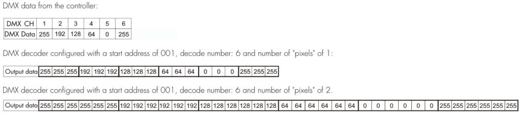
In the example below, we have a white pixel strip connected and each DMX input controls 3 LEDs.
Standalone RGB Controller Mode
- Short press the M key, when it displays P01 – P32 it is now in stand-alone mode.
- Press the ◀ or ▶ key to change the dynamic mode effect (P01 thru P32).
- Each effect has the option to adjust speed and brightness:
- Long press the M key for 2 seconds to enter setup.
- Short press the M key to switch the setting.
- Press the ◀ or ▶ key to setup the value of each parameter.
- Speed: 1 – 10 levels (S-1 to S-9, S-F)
- Brightness: 1 – 10 levels (b-1 to b-9, b-F).
- Long press the M key for 2s, or timeout will automatically occur after 10 seconds.
- NOTE: The unit will only enter stand-alone mode if there is no DMX signal so do not connect a wire to the DMX input.
Dynamic Effect List
- P01 – Red Race with White Base
- P02 – Green Race with White Base
- P03 – Blue Race with White Base
- P04 – Yellow Race with Blue Base
- P05 – Cyan Race with Blue Base
- P06 – Purple Race with Blue Base
- P07 – 7 Color Multi-Race
- P08 – 7 Color Race Close & Open
- P09 – 7 Color Multi-Race Close & Open
- P10 – 7 Color Scan Close & Open
- P11 – 7 Color Multi-Scan Close & Open
- P12 – Blue White Chase
- P13 – Green Cyan Chase
- P14 – RGB Chase
- P15 – 7 Color Chase
- P16 – Blue Meteor
- P17 – Purple Meteor
- P18 – White Meteor
- P19 – 7 Color Meteor
- P20 – Red Float
- P21 – Green Float
- P22 – Blue Float
- P23 – Purple Float
- P24 – RGBW Float
- P25 – Red Yellow Float
- P26 – Green Cyan Float
- P27 – Blue Purple Float
- P28 – Blue White Float
- P29 – 6 Color Float
- P30 – 6 Color Smooth Sections
- P31 – 7 Color Jump Sections
- P32 – 7 Color Strobe Sections
Control System Effects Integration
Download the Pixel LED Strip Effect Control System Integration Guide
Required Hardware:
Hardware Connections
Strip Connection for Less Than 10 Amps
Strip Connection for Over 10 Amps
Please note that these strips are directional as indicated by the arrow on the PCB. When linking more than one strip, be sure the arrows all flow in the same way. If connecting more than 2 strips, additional power to the + and – wires will also be required every 2 additional strips. This can be delivered from the same power supply with a separate home run.
DMX Decoder Configuration
The easiest way to achieve one of the 32 different built-in effects is to configure the DMX decoder for mode 2 operation.
- The first step is to set the DMX Address of the decoder. By default, it is address 1. If you need to change this, use the arrow keys to select a new value. NOTE: In mode 2 it will use 3 DMX addresses so if you select address 25, it will use 25, 26, and 27. Verify this does not conflict or overlap other devices on the DMX bus.
- Next, hold down the M and ◀ buttons at the same time to access the settings menu.
- The first parameter is the IC type. Use the ◀ and ▶ buttons to select “C18”.
- Next, press and hold the M button for 2 seconds to exit the menu (or wait 10 seconds).
- Now we will put the unit into Mode 2 by pressing and holding the M, ◀ and ▶ buttons at the same time to enter setup.
- Use the arrow buttons to select “d-2”.
- Press and hold the M button for 2 seconds to exit the menu (or wait 10 seconds).
You are now ready to integrate the control system. Add the new “Mode 2” driver that is available for free from our Resources page. Enter the starting DMX address you used in step 1 above and configure any additional properties based on the driver-specific instructions included.


Reviews
There are no reviews yet.