Specifications
| |
7” Indoor |
5” Indoor |
4” Indoor |
3” Outdoor |
| Voltage |
24 Volt |
24 Volt |
24 Volt |
24 Volt |
| Nominal Wattage* |
30 Watts |
12 Watts |
8 Watts |
12 Watts |
| Max Total Wattage |
37.2 Watts |
19.0 Watts |
12.2 Watts |
19.0 Watts |
| Red LED Wattage |
11.42 Watts |
5.88 Watts |
3.14 Watts |
5.88 Watts |
| Green LED Wattage |
9.82 Watts |
5.16 Watts |
3.07 Watts |
5.16 Watts |
| Blue LED Wattage |
8.23 Watts |
4.20 Watts |
2.90 Watts |
4.20 Watts |
| White LED Wattage |
7.75 Watts |
3.72 Watts |
2.90 Watts |
3.72 Watts |
| Color Type |
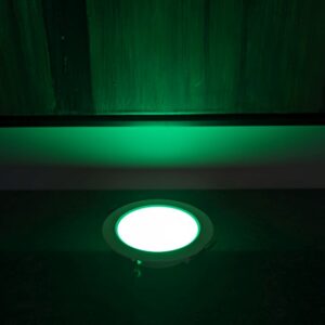
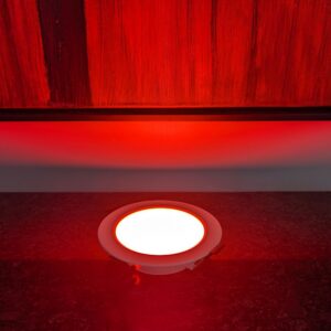
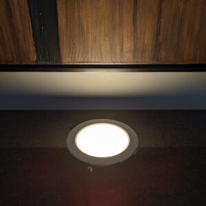
RGBW |
RGBW |
RGBW |
RGBW |
| Lumen |
1920 |
960 |
605 |
960 |
| White Temp |
4000K |
4000K |
4000K |
3000K |
| Size |
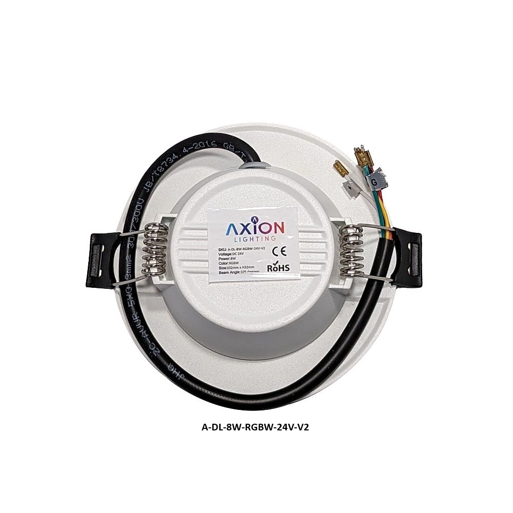
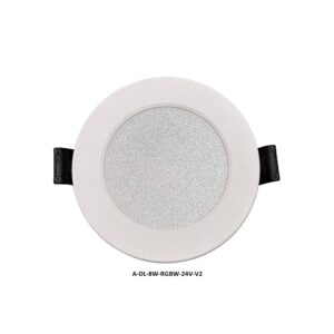
176 mm x 32 mm tall
6.93 in x 1.25 in tall |
136 mm x 32 mm tall
5.35 in x 1.25 in tall |
102 mm x 32 mm tall
4.01 in x 1.25 in tall |
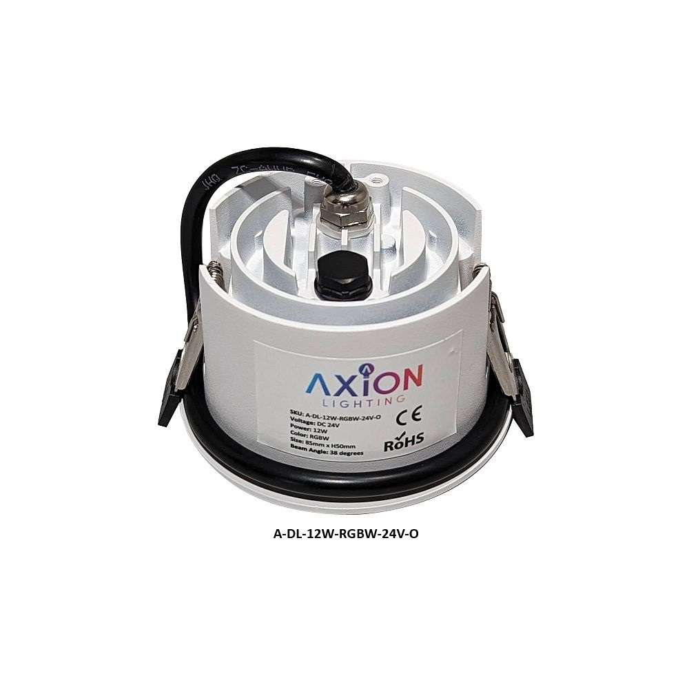
85 mm x 50 mm tall
3.35 in x 1.97 in tall |
| Cut Hole |
145 mm
5.70 in |
105 mm
4.13 in |
75 mm
2.95 in |
75 mm
2.95 in |
| Beam Angle |
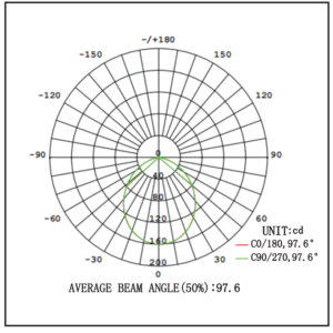
105 degrees |
105 degrees |
105 degrees |
38 degrees |
| CRI Ra |
80 |
80 |
80 |
80 |
| Housing Material |
Die cast Aluminum |
Die cast Aluminum |
Die cast Aluminum |
Die cast Aluminum |
| Warranty |
3 Years |
3 Years |
3 Years |
3 Years |
| Weather Rating |
IP20 – Resistant to dust or objects that are over 12mm in size. No protection against water jets. Indoor use only. |
IP20 – Resistant to dust or objects that are over 12mm in size. No protection against water jets. Indoor use only. |
IP20 – Resistant to dust or objects that are over 12mm in size. No protection against water jets. Indoor use only. |
IP65 – Completely protected against contact, the ingress of dust and water jets from all directions. |
* Nominal wattage is the standard draw at which the fixture has been designed to run using a combination of colors and/or white LED illumination. The expectation is that not all color LEDs and the white LED are being using concurrently, however, it is possible so care should be taken to account for the max power draw when sizing your power supply. Driving all the LEDs at once should only be done over short periods or damage to the fixture could occur.
Installation Instructions
Installation Requirements
- Before you begin installation, please verify that 24-volt power is off. It is recommended you disconnect the power supply before starting.
- When installing in a ceiling, it is highly recommended you do not cover the top of the fixture with insulation. It is ok for it to be surrounded by insulation, but adequate airflow will ensure the heat sync can cool the fixture and provide better longevity and performance.
- To help create a better seal between the fixture and drywall, installation of a vapor barrier prior can help reduce air entering/leaving the attic.
- Although this document does not cover the power supply or system integration, it is worth noting that all dimming happens on the DC output side and these low voltage fixtures should not be hooked up to a 120V or 220V dimmer.
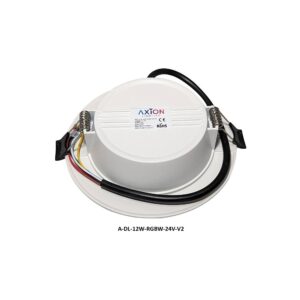
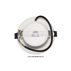
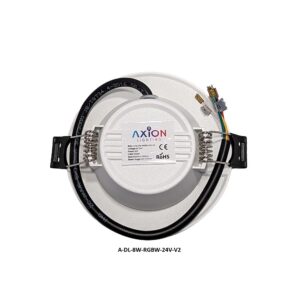
- Do not hold the fixture by the RGBW+ cable.
- Please check the contents of the package before installation for damage.
- We recommend bench testing before installation.
- ALL WIRING AND INSTALLATION SHOULD ADHERE TO LOCAL AND NATIONAL WIRING STANDARDS.
Safety
- The fixture is 24VDC; connecting it to 12VDC, 120/240/220 AC will void the warranty and cause permanent damage.
- Do not wire the fixture into a DMX decoder or power supply that is energized.
- All dimming happens on the 24V side and should be done with a compatible PWM device.
- Do not install in an environment that is fully sealed. The heat sink must have airflow to properly cool the device.
- Do not install in environments that constantly see humidity levels above 70%.
- Before servicing the fixture, disconnect power and allow time for it to cool.
- Use care when handling the fixture. Do not expose the device to chemicals or other substances which may be corrosive.
- Never soak or submerge the fixture in water.
Installation Instructions
- First, identify the location where the lighting fixture will be installed.
- Verify there are no obstructions above the area including beams, pipes, electrical wires, studs, etc.
- Cut out the provided template from the top of the shipping box and trace the cut-out hole on the ceiling.
- Using a drywall saw or other suitable device, cut out the installation hole.
- At this point, run your wire from the DMX decoder (or other control device) to the first fixture. Multiple fixtures can be linked together using a single home-run wire.
- The longer the run, the thicker or lower gauge wire is recommended to help prevent voltage drop.
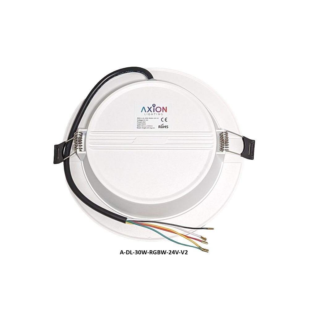
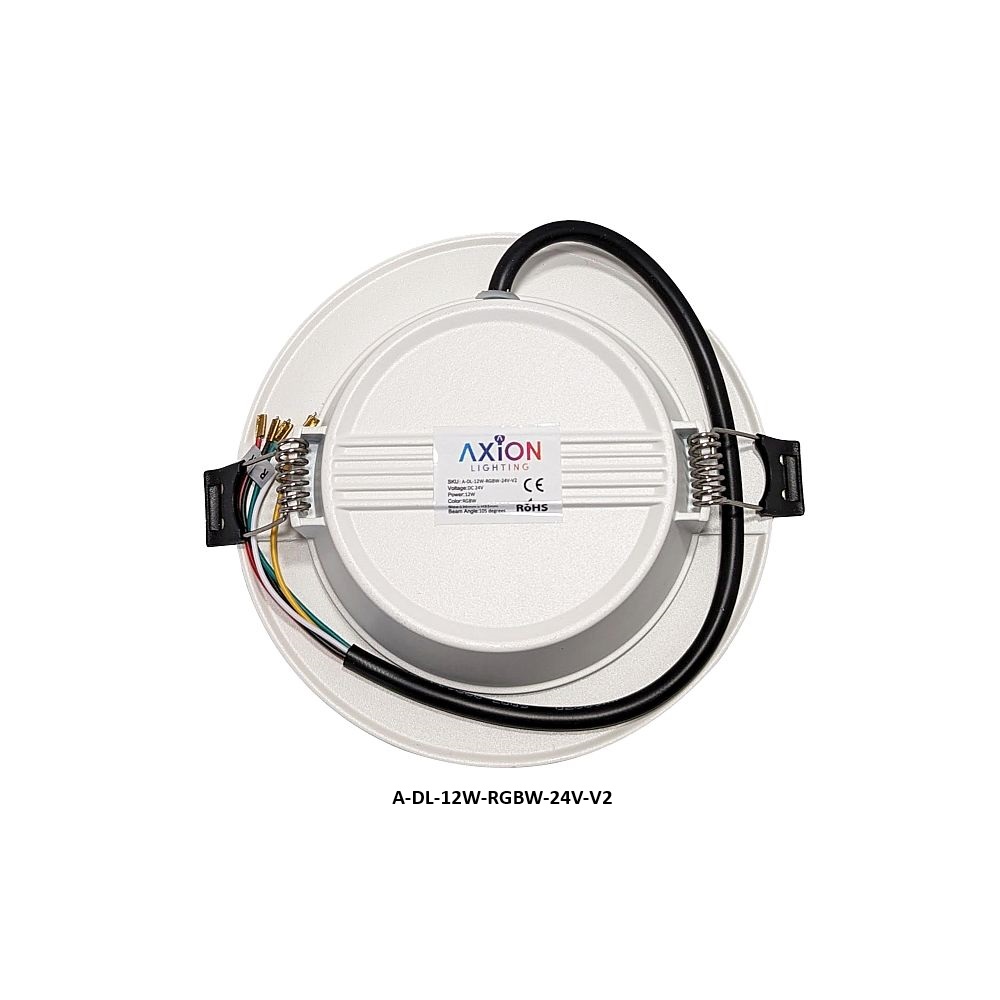
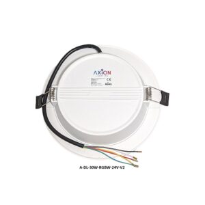
- You will need a cable with 5 wires if leveraging all Red, Green, Blue, and White LEDs (plus one for power).
- Wires can be joined using any suitable appropriate for the gauge wire such as: dolphin connectors, butt connectors, crimp connectors or even soldering.
- Once the wires have been properly joined, place the fixture into the ceiling.
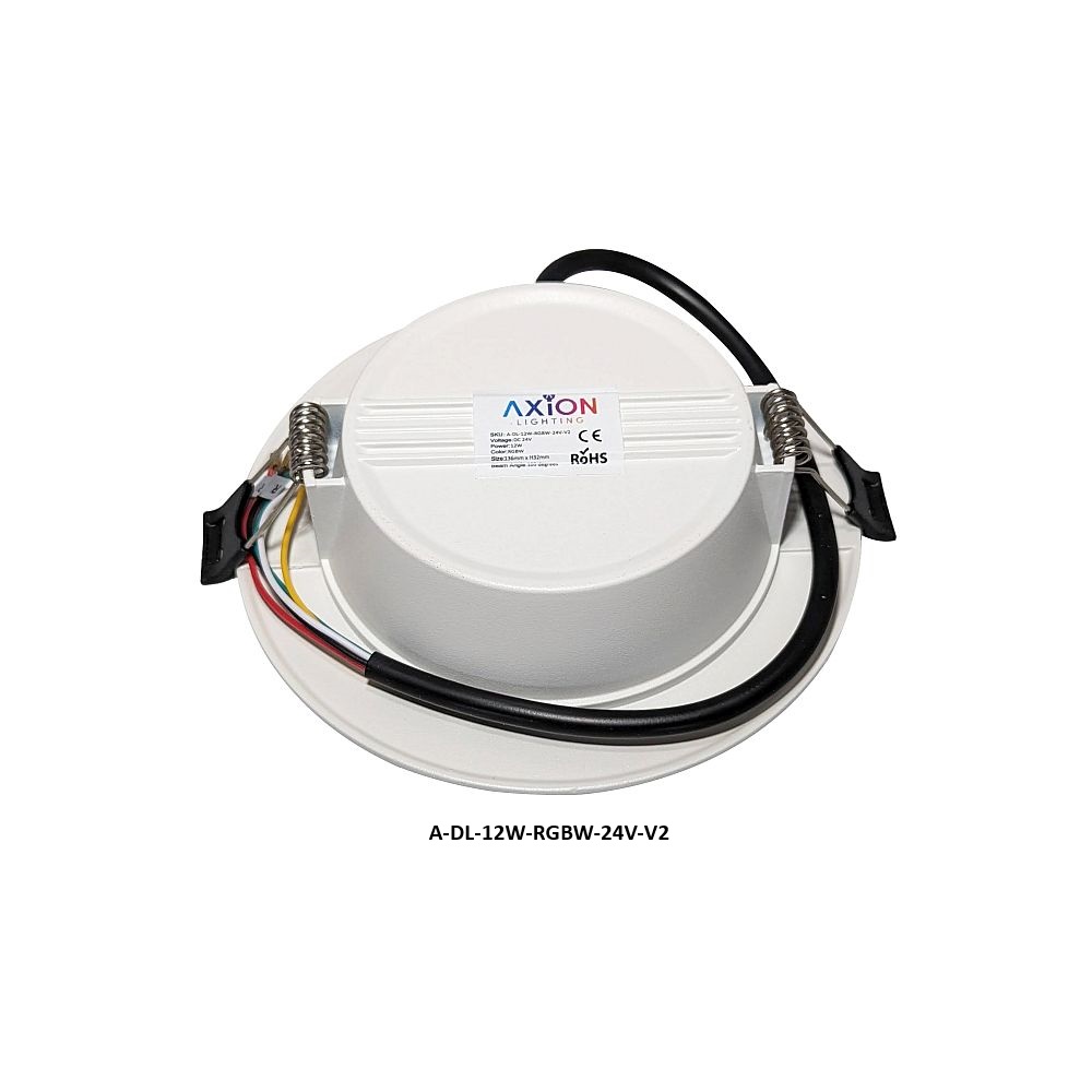
- Push up on the spring flanges so they extend up towards the heat sink, then carefully work the light into the hole. Once inside the cut-out hole, release the spring flanges and it will fully seat.
- Apply power and test that you now have control. If certain colors do not seem to work, verify you have a solid connection.
Wiring Color Code
Recessed Downlight Wire Color Code
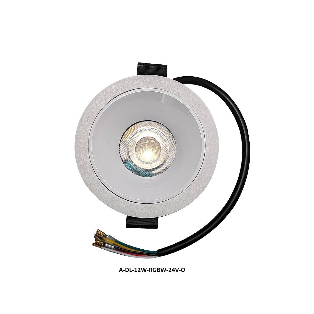
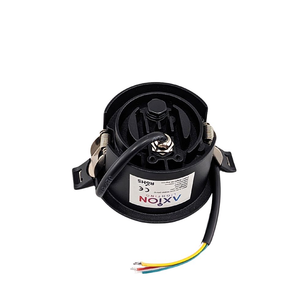
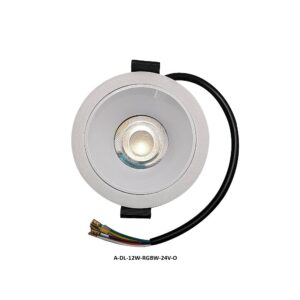
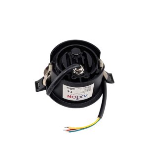
Red Wire = Red LED Color
Green Wire = Green LED Color
Black Wire = Blue LED Color
Yellow Wire = 4000K White LED Color
White Wire = 24v Power Positive +
Ideal Wiring Strategy
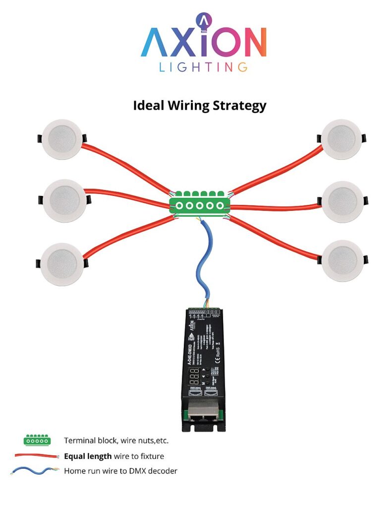
The best way to wire our recessed lights is to maintain as close to the same length wire run back to the DMX decoder or other control apparatus as possible. In the scenario below, the blue wire is a home run to the attic as centralized as possible to the 6 RGBW LED lights. Then, from that location an equal length wire is run to each light and joined using wire nuts, terminal block, dolphin connectors, etc. This will result in an equal amount of power going to each light so that you minimize voltage drop and potential brightness deltas between fixtures.




Reviews
There are no reviews yet.